I use a lot of these connectors, but with a caveat the connector is going to live in a dry environment. If your connections are going to be exposed to rain and saltwater even if only rarely use the the traditional solder/crimp connectors. Like all connectors there are some pluses and minuses, starting with varying db losses, the need for special tools, and so on. There is also a valid school of thought that the soldered versions are better, and I won't disagree with this. However my sense is failures are in most, but not in all cases, more driven by the level of corrosion exposure than the type of connector used. Personally I've had good luck with the crimp-on units, but you have to do it right and this is what I'm talking about.

I'm installing a splice with one today. For reasons that aren't clear to me the VHF cable was cut. I can't believe it was done deliberately, and you would have thought someone would have noticed the VHF radio couldn't receive squat, but that's another story.
So I'm going to show you how to properly use the Shakespeare Centerpin splice, and this is identical to the process used for the VHF radio connector.
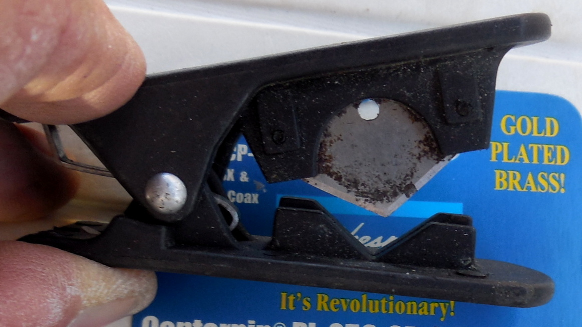
The first thing to deal with is cutting the cable, and this is important. That little Parker tool to the left is one of my favorites. It's actually used to cut 3/8" plastic hydraulic tubing but you get a perfect results cutting coax cable with it.
There are other ways to do this like my time tested beheading approach. Take the cable and place it on a cutting surface. My plastic drill bit box works well in situ. Take a utility knife with a good blade, line it up square on the cable and then use something with heft to give the blade a good crisp downward whack. The handle end of a larger screwdriver or the ilk does the trick. Make sure your fingers are well clear of the sharp Vorpal blade at all times.
There are other ways to do this like my time tested beheading approach. Take the cable and place it on a cutting surface. My plastic drill bit box works well in situ. Take a utility knife with a good blade, line it up square on the cable and then use something with heft to give the blade a good crisp downward whack. The handle end of a larger screwdriver or the ilk does the trick. Make sure your fingers are well clear of the sharp Vorpal blade at all times.

What you need is a square cut that doesn't deform the cable and has clean sharp edges. Straggling wires hanging out anywhere are a absolute no no. You won't get a good cut with scissors, wire cutters or other less than very sharp implements. Good, if you pull this off well, and I think you can, you're almost home.

Now for a couple of assembly pre-steps starting with figuring out which of the two cable sizes that fit this connector you have.
For most recreational boats it will be either RG8X, or RG58CU. It's easy to tell which one you have. Look inside the package and you will find a small plastic bag containing for a splice, two small rubber o-ring gaskets and two small clear plastic caps.
Ding Ding, it's time for an "Installer's Tip". This tiny little bag weighs almost nothing and the slightest of zephyrs will blow it overboard resulting in the loss of maybe three cents of merchandise that will send you back to the store to buy a whole new package, if you needed them. I know for a fact this can happen, more than once.
Back to the story now. The little plastic caps fit only on RG58CU cable. They don't fit? Then you have RG8X cable. If the RG8X doesn't fit either you bought the wrong connector and likely have the much larger RG213 cable, or unfortunately you're maybe holding the TV coax cable in you hand.
What's next is to slide on the needed pieces in order on the cable. Screw this part up and you get to buy another connector kit. Once you have started to depress the pins you can't un-ring this bell. The knurled threaded cap goes on first and then the o-ring. The next step is to push the cable with a twisting motion into the connector body (if using RG58CU cable you need to put the little cap on the cable end before you push and twist it in). You have to seat the cable fully onto the pin inside. If you're using the little cap it has to end up being fully inside the connector body.

A little more nuance to deal with left. You want the cable to come straight out of the connector, not bent at a wonk angle. Grab your needle nose pliers and using the ends of the pins gently press each pair of until they just touch the cable sheath.
Now check again that your cable isn't at a wonky angle. All Good? The pins push through the sheath and connect to the shield. With the RG8X cable the pins need to be almost flush with the cable sheath. Do this with the smaller RG58CU cable and you will likely press the pins into the center core, again causing a trip back to the store. So the rule of thumb is to crimp a bit moving to each pin pair, and see how the cap fits. If it doesn't, crimp a little more making sure you're doing it evenly, and try the cap again. The pic above is a RG58CU cable and it's not yet crimped down enough yet.

The last step is to screw the cap on with the gasket rolled down. This may require using pliers or the ilk to tighten them. If it's too tight, crimp a tiny bit more, and try again. Now give your radio a good check to make sure your getting a good signal out of the antenna. Ahem, make sure the antenna is up when you do this.
To summarize, it's for dry locations, you need a good clean cut cable cut, the cable has to be seated all the way down into the connector body, crimp evenly in small increments going around in a circle, and when the cap fits you're done. Good job, now make sure you have a MMSI number programmed into your VHF, and you have a NMEA connection.
No comments:
Post a Comment
Note: Only a member of this blog may post a comment.