Strip Molding 101 from Boatbuilder magazine

Sunday, August 29, 2010

Transducer meditations


The installer sits down in a lotus position behind the hull, lights incense, clears his mind of extraneous thoughts, slows his breathing, and enters a trance. He sees the hull sitting in the water, and starts to move it forward at a very slow speed. The flow of the water passing under the hull is smooth, and laminar.


In his minds eye, he picks up the speed. The water flow becomes less laminar, and a turbulent boundary layer starts to develop next to the hull. This boundary layer is caused by friction of the hull as it passes through the water.

As water travels down the hull, it finds its first obstacle, a through hull fitting sticking out from the hull. As the water flows over, and around the fitting, an adverse pressure gradient is formed behind it. As the speed further increases, the water behind the object becomes increasingly turbulent, and is swept aft down the hull. The picture below is a computer model of a fluid passing over a sphere. Note that the flow is laminar at the front of the sphere, but becomes very turbulent at the back side. This is how water behaves as it passes over a hull water inlet, and your transducer doesn't like this.


As the installer studies the water flow traveling down the hull he looks for a spot with the smoothest water flow to mount the transducer. It has to be clear of the turbulent flows coming from things sticking out of the hull, and the transducer bottom must be mounted lower than the boundary layer turbulence that is against the hull.


Looking at the port side he spots a large plastic water pick up. That's okay, it would be better if the transducer was on the starboard side anyway.


Doh! There is another pick up on the starboard side. The meditative trance abruptly comes to an end. Why couldn't the builder have put both pickups on the port side? There was plenty of room for both, and the water flow would have then been reasonably clean on the starboard side. There is this weird thing about the desire for symmetry, even at the expense of performance, especially in an area you don't normally see. This is a typical example of boat builders not thinking about what kind of equipment will be installed on the boat.

There is actually some art, along with the science involved in placing a transducer on a boat, and you really do have to try to visualize how the water will flow under the hull. The transducer bottom needs to be below the turbulent boundary layer next to the hull, and must be clear of upstream turbulence from inlets and the ilk.

Avoid placing the transducer behind protruding strakes, because they can carry air entrained turbulent water aft to the transom. You also need to make sure that turbulence coming from water flowing around the transducer doesn't cause propeller cavitation, or interfere with the cooling water flow to an outboard motor.

So the basic rule of thumb is to get the bottom of the transducer into the smoothest possible water flow, which translates to getting it as far below the hull as possible. In many cases, it is a Zen thing. The transducer will work okay on this boat, but I would have had an easier time placing it if the starboard side water pick up was on the port side.

Keeping the hull clean is important to transducer operation. The dirtier the hull, ie barnacles, and other icky growths, the more turbulent, and thicker, boundary layer becomes, and it will affect transducer performance at speed.

And a last gentle reminder, at 20 knots, when your depth finder tells you it is too shallow, it is to late.


The photo of the computer model is from an article written by Claes Johnson, and Johan Hoffman, and is no longer available online.


Sunday, August 22, 2010

"Tools", an on-line novel project

I am starting a second writing project, beginning in November. The intent is to write a science fiction novel, on-line, a chapter at a time. I am going to continue writing "The Marine Installers Rant", while this effort is ongoing. It should be fun, at least for me. I have posted a link on the right to the new page. There is not much there now, except an intro draft, and I am still playing with the template. I will squawk about this, when the site gets close to being  finished. 


Saturday, August 21, 2010

It seemed like such a good idea at the time.


A friend of mine, Mark, got a "Stripper" canoe kit as a gift one year from his wife Cathy. The kit consisted of a pile of bead and cove strips, precut rails, a few assorted pieces of wood, and about 10 pages of instructions. He was clueless about how to actually build it, and asked me for some help. I carved out some space in a building that my dad was using to build a 35' John Marples Searrunner trimaran. My dad never wanted to use the boats that he built, and rarely did. He was a civil engineer, and just loved the intellectual exercise involved in building boats.

I had never built a Stripper craft, so as I reviewed the plans, I noticed the instructions said you were to use small brads to nail each strip to the frames to hold them in place, and when the hull was done, you pulled the nails out, and filled the holes with toothpicks. I thought this was a stupid way to do this, and you would end up with a hull that would have hundreds of obviously filled holes in it.

So when I lofted, and built the construction frames for the hull, I drilled holes along the edges, and used small C-clamps to hold the strips in place instead of nails. The first few strips were glued in place, but it was hard to get a good fit in between the strips where there was no frame to secure it to, so I  milled small U shaped pieces of wood. These pieces of wood would fit on top of a strip, and had a string attached to it, with a brick at the other end. This weighted down the strips while the glue was drying. Construction moved at the blistering pace of about 8 strips per day.

Now, I don't want you to think at this point that I was actually building this little vessel. I lofted the frames, gave instructions on how to do it, and my friend Mark would come in and actually do the work, while I studied the problems encountered, and his progress. So along the way, I had a slowly dawning epiphany that there might be a better way to build this type of boat. The things that I didn't like about the construction technique were the problems in getting a good fit in between the strips, and when the hull was done, you had a polygonal (lots of flat surfaces) structure that had to be hand faired into a curvaceous shape. Although this wasn't hard to do on the outside of the hull, it did expose any gaps in the the glue, and these gaps had to be filled, and again sanded, and sometimes you had to remove a lot of hull material to get a good shape to the hull. On the inside of the hull, there was little you could do with the polygonal shape, except sand off the excess glue, and the pace of construction was glacial

After thinking about this for a while, I tried a little experiment. The canoes strips were a 1/4" of an inch thick by 3/4" wide. I took a plank of western red cedar, and cut a bunch of strips that were 1/8" thick by 3/4" wide. I made a small curved mold, and attached a bunch of screws around the edges. I took the strips, taped together into a small sheet and laid them out on the mold, and used string to lash them into place. I put a piece of four ounce fiber glass, on top of the strips, rolled on epoxy, and then lashed a second layer of strips on top. I covered the layers with plastic, hooked up a vacuum pump, and went away for a few hours.

After the epoxy cured, I came back to look at what had happened. The two layers of western red cedar had shaped themselves to the shape of the mold. The surface was fair inside, and outside. I then epoxied four ounce glass on the inside, and outside. The result was outstanding. Strong, tightly fitting planks, good looking, and the exact shape of the mold. "Strip Molding" was born. You can learn more about Strip Molding, at the link to the right, titled "Strip Molding 101". This is a scanned article from Boatbuilder magazine, I wrote in 2000.


In a great burst of enthusiasm, I decided to embark on an adventure in boat building, and started to build canoes, because you only needed one mold to make a symmetrical, mirror image vessel. I studied the materials carefully. Aerospace grade epoxies, clear acrylic aliphatic urethanes with UV inhibitors, cast bronze fittings, western red cedar, and Honduran mahoganies were all the materials of choice. The results were stunning. No fasteners, perfect hulls, beautiful woods, strong, light, and with clear, sun resistant coatings that would last for many years without maintenance.


I built molds for John Marples' Gull and Daffy dingies, with sail kit options, and I then went back and started to play with canoe options. One of the first things I added, was a trolling motor option. A removable oak bracket could be attached, and a Minn Kota electric motor could be attached.


To power it, wiring for batteries was embedded under the keel strip connecting the fore and aft compartments, and compact AGM batteries could be placed the the fore and aft compartment. A trolling motor outlet was installed, along with a 12VDC outlet, used for charging, and other needs. The little vessel had a range of about 12 miles, at about 4kts. If you slowed down, the range increased.


You gotta have drink holders for the adult, or otherwise beverages.


Since you have 12 volt power, you can have Orff's Carmina Burana blasting out of the speakers while underway. It still sends shivers down my spine.


As long as you have batteries, you might as well charge then while underway, and a mahogany framed solar panel was added. The panel was not adversely affected by shadowing, and had a clear plastic coating, so it could double as a table, and the caned seat backs were made reversible


So out of these improvements, came the "Piece d Resistance" the Solar Electric canoe. With the solar panel, the range increased to about 15 miles on a sunny day. I took one on a three day camping trip, 26 miles down the Peace river, and never once touched a paddle, although I had them. The solar panel was able to shove enough extra charge into the system, over the three days to give me power to spare for the trip.


All of these boats were beautiful, and cost competitive. The solar electric canoe sold for $5500. As a comparison a new wood Old Towne canoe with a clear finish now sells for $7800. But for love or money, I couldn't sell enough to make a profit. I did boats as furniture, spent thousands on brochures, advertising in the New Yorker, and Wooden Boat magazines, and did boats shows, but to no avail. I sold a lot, but never quite enough to make a profit. In the end, I did find a outlet selling them in high end art shows, but the life of a nomad with a big truck full of boats was not what I desired. After three years of trying to make it profitable, I again had a slowly dawning epiphany. People buy expensive high technology boats, and keep them outside in a highly corrosive salt water environment, and by waiting for a few weeks, something will break, and the owner will call you to get it fixed.

So I shut down, the boat building business, and started to repair boats, and install marine electronics, and I instantly started to make money. Okay, so why couldn't sales and marketing genius boy make a buck with such a cool product? I have had a long time to think about this. The first is geography. Southern Florida, is not exactly a hot bed of small wooden boat enthusiasts. I think, had I been doing this in the right northeast location, the reception would have been better. The second reason is you had to see, and touch the boats, to buy them. Despite all of the advertising, only a few boats were sold from it, and the third reason was they looked so good, people were afraid to use them, and I know for a fact, that most of them are hanging in the summer house as an "object d art".

It seemed like such a good idea at the time.

Tuesday, August 17, 2010

Robotics, automation, and the single boat builder, a short look forward.


Sometime in the eighties, I was was a salesman for a robotics company (PaR), and was looking for new gantry robot markets. I called several of the larger boat building companies, and asked if I could come and look for possible applications of this technology. One of the companies I spoke to was Searay, and a nice young guy named Rob Parmentier, agreed to meet with me. Rob was a gracious host, a good listener, and spent several hours with me, but alas, the time was perhaps too early for this technology, and no order would be forth coming. Rob, I understand, has done well with Searay, and although I don't think he would remember the several hours he spent with me, I would hope that the conversation would have at least piqued his technological curiosity. Most of the other companies, just said they weren't interested, and didn't need any automation.


A PaR gantry robot cutting a hull mold plug.

In my youth I was as a rigger on the Excalibur line at the shiny new Chris Craft plant in Bradenton Fl. The process of building a boat then, went like this. A bunch of guys in the lamination shop would be making, cleaning, prepping molds, and spraying them with gelcoat. Then out came chop guns, laying sheets of fiberglass, and using lots of little metal paint rollers to squash it all flattish. A bunch of man hours later you had a hull. When the hull was cured, jigsaws, and grinders were used to gnaw the excess fiberglass away following a line drawn by someone with a Sharpie. The same process would happen to the the top/deck structure. The deck was placed on the the hull, usually with a lot of pejorative vocabulary, pry bars and a couple of big guys jumping up and down on top of it. Eventually the two pieces were finally screwed together.

The now sort of finished deck and hull was placed on a dolly with wheels, and it was pushed onto the finishing line. The engine crew would get it first, and when they were done, everyone would stop, and push every boat on the line up one space, to the next station.

I did final rigging. That consisted of taking parts made by the wood shop, often covered with a carpet like substance that we called monkey fur, and installing them in the boat. This included bulkheads that separated the cabin from the cockpit. Sometimes the parts fit okay, sometimes they didn't, but the carpet beading stapled on the edges, made them look like they fit, in most cases.

Each boat had several molds, and none of them were identical, close mostly, but again not identical, and the halves were not exact mirror images. The mold makers were talented, but like all hand made products, there were differences between each mold for the same vessel. The end result was a lot of parts had to be modified, tweaked, or custom made, and  this was a  time consuming task.


A PaR gantry robot waterjet trimming a fiberglass part

So, where do we stand today, with boat building technology? Things are better in many ways. CAD designed boats are becoming more common. CNC cutting systems now cut out wood, and Starboard parts. Gelcoats, epoxies, and resins have made a quantum jump in quality, and more boat builders are willing to entertain new manufacturing technologies. Good procurement, inventory management, and scheduling software is now becoming common. But sadly many boat builders still build boats like they did in the seventies.


A PanelMate CNC cutting system

In the US, cars are built, even in a bad year, (2009) at the rate of about 10 million vehicles per year, by a handful of manufacturers. The fact that you can buy a new car, for $15,000, made of thousands of parts, that will work reliably for years, is a testament to engineering, automation, and most of all volume. You need a car, but you want a boat, and although the numbers are difficult to come by, there are over 300 US based power boat builders, all competing for a bite of, and again the numbers are hard to find, about 250,000 units or so this year. No matter where you turn in this market place, you have a huge number of competitors, all chasing the same clients.  


A CAD hull design by 3D Boat Design

So at this point, I am going to put on my conical hat, with stars and crescent moons on it, cast my chicken bones, and attempt to prognosticate what builders will need to survive in the coming decades.

At the very top of the list is CAD designed boats, and robotically cut hull molds. CAD based technologies allows you to iterate, and optimize designs. Robotically cut molds, assure parts fit correctly, and allow for more complex shapes to be integrated into the designs. If you don't do anything else, do this. Everything will fit better inside the boat, if the hull is precisely made. If you can't afford the equipment to do this, use a subcontractor, they are out there.

There is no point in doing the above, if you can't properly trim the parts after they leave the mold. If you know exactly what the shape of the part is, it is easy to automate the trimming process.

Since you now have precise molds, you can now use robotic spraying robots to apply mold release compounds, gelcoat, chopped glass, and other similar coatings. The robots can spray the exact amounts, at the exact thicknesses. You will gain material savings, time savings, quality, less warranty expense, and reduce personnel exposure to sometimes very nasty chemicals.

Configuration Control is critical to after sales dealer, and technician support. This is the system that keeps track of what parts, and materials that went into a particular vessel, and management of all of the engineering drawings. There is nothing worse than calling a manufacture, to get a wiring diagram, and finding out it doesn't exist, or you're trying to match a fabric, and no one knows or remembers where it came from. Wait a minute, I will walk out on the line, and see if I can find one being built, and e-mail you a picture of where the thingamabob was installed.

There are many other items that can be on the list, but these are my big four. We can add to this list environmental remediation systems, green technologies, interior component fabrication technologies, and much more.

So my summary goes like this, the more forward looking companies will prosper when the financial outlook improves, because they will be more efficient, their products will sell for less, be better quality, and more supportable as their technologies continue to improve. The companies, that are not making this investment, will falter, and fall by the wayside.

After this little discussion, I want to point out that there are some boat builders out there aggressively adopting these technologies, and notably Brunswick, Yamaha, and Stingray. Go Google these companies, and I think you will be pleasantly surprised, and when you are shopping for a boat, ask about their manufacturing technologies, and especially if they have a configuration control system.

My last thought for boat builders is that when nice some salesperson calls, and wants to tell you about a new technology, take some time to listen. He or she may have just the thing you need to give you an edge.


The Dodge Boat works circa early 1930's. They closed in 1936. Funny how it reminds me of a boat manufacturing line I saw a few months ago. 

Monday, August 16, 2010

That fish box is strong enough, most of these guys just use them to keep the beer cold anyway.


Nothing better than a good fish story, especially when the fish is so big, you can't spread your hands wide enough to show people how big it really is. The fish is a Warsaw grouper (hence forth referred to as Gigantor), caught in about 650' of water about 140 miles off the coast of Sarasota, and the best guess is that it exceeds 200 lbs. It took three people just to get it into the boat, and as you can see, it dominates a 6' fish box. I will add the actual weight in the comments box, when I get it later today. 


The boat is a popular, and higher end center console fish boat, and in general, is a well constructed vessel. The owner loves to fish, I mean really loves to fish, and he does a lot of tournaments. The boat is crammed full with fishing gear, coolers, lot of extra gas containers, and bean bag chairs for over night expeditions.


So enough of Gigantor, see that black crack in the picture below, at the edge of the fish box? That is not where the fish box should be. The back of the box has fallen down about three inches, and now water, and or ice can slosh out of the back end of the box into an area, I suspect was not supposed to have water at all.


It was hard to tell exactly what had happened, because the box had Gigantor the grouper in it, and numerous spectators were hovering around, but the aft center of the box didn't appear to have anything fastening it.


The box seems at first blush, to have been just tabbed with fiberglass in the corners, and under the weight of the fish, and ice, the tabs just failed. The seas were calm, so I ruled out the fact that pounding in 4' seas, with Gigantor in the box could have exacerbated the problem. The attachment was just not adequate, and you can see the torn fiberglass in the corner below. Bad design? Bad manufacturing? I don't know, but this builder can do better than this. The repair will be interesting, because all of the fish box installation was done prior to installation of the deck. I'm sure that this builder will take care of the problem, but it shouldn't have happened in the first place. If you want real fishermen to buy the boat, the fish box has to be able to support real fish. Gigantor has had the last laugh as payback for his untimely demise, and all the beer was kept in real coolers.


Just as a side note, I will amend this blog tomorrow with a couple additional photos of the grouper on the scales. The final measured weight is 206 lbs. It is worthy of the name "Gigantor", and boy did it produce some fillets.


Jason Boyll, from the fishing team" Get'n After It!" emailed me a picture of Gigantor hanging on the scales in Cortez Fl. It is impressive, and these guys are are fishing monsters.


Sunday, August 8, 2010

You dirty rat you, you're going to meet old sparky.


This isn't a glamorous story, but someone has to broach this elephant in the boat. In the wide world of boating, there is hardly a location where you couldn't have a rodentia problem, and boats in Florida, are certainly no exception. Rodents are one of nature's sturdiest mammals, are ardent adherents of Darwin, and can do huge damage to boats. They can fit through tiny places, breed at a prodigious rates, and can gnaw through both wiring, and fiberglass. They use your vessel as a public restroom, leaving behind less than lovely odorous wafts of uric acid. You want your guests to have an experience that will be the talk of the yacht club for years to come? Just have a 14" black fruit rat make an appearance in your cockpit during happy hour. What fun all will have with the screams, spilled drinks, and upset appetizer trays.

Kate and I own a hysterical (it's not a typo) house built in 1956 and designed by Jack West. It is a Sarasota School of Architecture home, and we love it, except for its seemingly endless 5000 sq foot flat roof. One of the nice things about the home, is the line between inside, and outside can be fuzzy, and as a result we sometime get unwanted guests, including "Whipped Tailed Squirrels" (Kate's code word for rats), and other occasional unwanted visitors. Through the years I have become adroit at critter removal, although I'm glad there are no You Tube videos of some of my gyrations during the removal process, and yes, under the right circumstances, I can make some less than manly, high pitched squealing noises whilst under extreme critter duress.

Noah's Ark stopped first in Florida, and got rid of some of his annoyances, and the rat below is an example. This is a Gambian Pouch rat, and can be found in the Florida Keys.


Before you rush to cancel your Florida vacation, most of us don't encounter rodents of this size, but like all places I have ever lived, there are rodents everywhere. Mice, or chipmunks who moved in the ski boat at the cottage over the winter, Norway rats, squirrels and many other local variants. 

So we will start the discussion on how to remove the offending critters from your boat, with what you shouldn't do, and that is to poison them. It does them in for sure, but the typical result is they crawl into some inaccessible crevasse in the boat, and then die. Not good, period. The smell of an overly ripe, bloating member of the rodentia family is not what you want on your vessel. Do you remember the urban legend about the new Corvette that was on sale for $500? The catch was the owner died in it, and you couldn't get the god awful smell out of it. After watching "Myth Busters" test this legend with a Corvette, that had a couple of dead pigs inside it, and from my own personal experience, I find this to be excruciatingly true. It is almost impossible to get the smell out.

So the second option is traps. They come in many flavors, and designs, ranging from the very basic finger mashing, spring loaded medieval traps we all know, to high tech devices.


Since I can profess to some experience in this field of endeavor, I am going to introduce you to with a drum roll to the Rat Zapper 2000, or as we affectionately call it, the "RZ2000, Harbinger of Death".


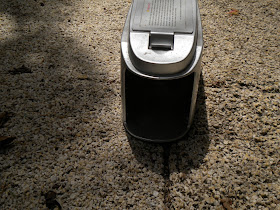
This is a technological marvel, and it sends shudders throughout the rodent world. It is about the size of a loaf of silver colored bread. The front has a grill that looks like a Buck Rodgers version of a modern locomotive. It would be a stylish accoutrement to any modern home's decor.


The top of this messenger of rodentia death holds four D cell batteries. There is a power switch and two associated LED's. The green one indicates it is armed, and the red one blinks, if there has been an execution. There is an 1/8 inch mini jack that allows you to plug in a remote LED light, in the shape of a mouse. On a boat you can place it on the dash, or in a window. This allows you to see from afar whether the RZ2000 hath smote a critter, or not.


The front of the RZ2000 is hollow, and open to the back, or front grill depending on your perspective. You take some cheap dog food, and drop five or six pieces inside, and tip it up so the dog food rolls all the way back to the grill. You then put a couple of pieces of dog food at the opening. Place it against a wall, or bulkhead, and turn on the power switch. The green LED flashes, and lets you know it is charged and ready to go. Mr. Rodent doesn't like open spaces, and prefers to move along walls.

What happens is, the vermin smells the food at the entrance, and dines on it. Smelling more food at the end of the trap, it walks in, on a metal floor, with a second insulated metal floor near the front. As the rodent moves towards the front its back legs are on the ground plate, and when its front legs touch the insulated plate electrical carnage occurs. A fully charged capacitor discharges a huge load of electricity through the critter. and it expires on the spot. No mess, no noise, no fuss, and one blinking red LED alerts you to the carnage. When the red LED blinks, you get your red medical waste bag, or in my case, it is a couple of plastic grocery bags, dump the critter into the two bags, tie the bags up tightly, and drop the bag into the trash. You never have to touch the critter, or boil your hands in bleach afterwards.

You can buy the RZ2000 at lots of locations online, and no, I am not being compensated by the Victor Trap company for the article, but I did find a small pile of acorns outside my back door, with a tiny note saying "There is a lot more, where these came from, if you don't publish this story".

Sorry  Mr. Kapoor, I really meant to spell it Rodant. You can find out more about Rodant Kapoor and other characters in the Ruby, Galactic Gumshoe stories from ZBS Foundation. I have been a fan for decades.

Thanks to Ranveig Thattai of Norway for the use of the "Mouse in the mouse trap photograph" via Wikimedia.org

Saturday, August 7, 2010

Crazy mouse is dead, more from PC purgatory.


Since I wrote the story  "PC" purgatory, I had looked everywhere, for a Crazy Mouse problem solution and had received a lot of advice, but none of it worked to date. I asked for help and got it. My friend Alan had forwarded several possible options, and among them was this  link as a subset of  a young fellows home page
.


I posted the possible solution on Panbo's forum, and Henning Durr gave me encouraging words regarding the viability of the solution. I installed the registry patch today, and it worked perfectly. No more crazy mouse, with three serial GPS's plugged in. No more disabling serial ballpoints, it just worked. This was an XP system by the way, and although I think it will work with Vista, and Windows 7 tread carefully, and I think sobriety is required while doing this, we don't want an ARI (alcohol related incident)  to occur you know.

The solution is simple, and consists of  using Regedit in the PC to change two numbers. The changes are below:

[HKEY_LOCAL_MACHINE\SYSTEM\CurrentControlSet\Services\sermouse]
"Start"=dword:00000004 (the 4 was a 3 before)

[HKEY_LOCAL_MACHINE\SYSTEM\ControlSet001\Services\sermouse]
"Start"=dword:00000004 (the 4 was a 3 before)

If you want to go back, just change the "4" to a "3", and you can have the crazy mouse back. By the way, your serial mouse will no longer work, so get a USB mouse before you start this, if you need to. I just went into the registry and manually changed the values. It took about ten minutes to do. If you are faint of heart, find a 12 year old kid to do it for you. Why does it have to be so complicated?

Thanks JamieZX, clever patch, and a good problem solution.


Searay redeaux, and the "Laws of unintended circumstances".

 This is a make over story, that also illustrates the "Laws of unintended circumstances." The vessel below is an older, but well loved, and cared for Searay. The chartplotter you see below (upper left) is a old Northstar unit that finally bit the dust. The Furuno below it is an older, but fully operational GPS chartplotter, and radar. After discussing what to do with the owner, he decided to install a new Garmin 5212 touch screen unit to replace the now deceased Northstar, and since the older Furuno radar was still working well, he would keep it in place.


Searay, and many other builders, used burled wood looking plastic panels in their consoles. The exact match to the existing panels is no longer available, but the owner found a 2' X 4' piece that was a close match, and it was decided to use the new plastiic for the location where the new Garmin was going to go, and to replace the lower Furuno's panel with the same material. So out come the units, leaving two gaping maws in the console.


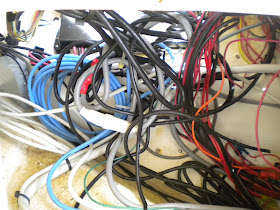
So far, everything has gone according to plan, the units came out, along with the old panels. The panels were delivered to Delcraft for fabrication, and unbeknownst to me, the "Laws of unforeseen circumstances" were just getting ready to go into effect. Behind the Furuno is what I call a "Spaghetti Bowl". These occur through the years as layers of new wiring, get laid over the old wiring. This was also exacerbated by the owner cutting a lot of wire ties, in an troubleshooting effort to identify the now defunct Northstar wiring.


It's not that I have a social conscience, I was a salesman for thirty years, but when I saw the spaghetti bowl behind the Furuno, I couldn't just leave it that way, and I asked my young helper to pull the old Northstar wiring out, and clean up the mess. The boat was stinking hot, and along the way, I was told he found a red wire that wasn't attached to anything, and what should he do with it? I'm not surprised that you find extra wiring, especially in an older boat, and I just said "tie it up".


After the wires were tied up, the new Garmin 5212 was tested, the software was upgraded to the current level, and I was pleased with the appearance of both the new Garmin, and the two new panels. The work looked factory original, and I don't think a visitor could see the slight difference in the color of the new panels.


Anyone who repairs anything, whether it is a boat, car, or plumbing, is familiar with the phrase, "Everything worked perfectly on my whatever, until you fixed the whatever". "The "Laws of unintended circumstances" come in three less than tasty flavors.

The first flavor is "Bile." This wretched flavor comes from someone who knew it wasn't your fault the whatever is broken, and is just trying to see if you will fix the problem for free. Fortunately, I have only had this happen a couple of times, and these people are no longer clients. 

The second flavor is vinegar. This flavor occurs when the client, thinks you broke it, but you really didn't. You changed the bow light fixture, and now the radio in the console is broken. These apparently unrelated events can link together, in an owners mind, in many weird, and wondrous ways. Lets see now, they both use electricity, I have a beard, Abraham Lincoln has a beard, so I must be Abraham Lincoln. You go to the console and pull out the rusted hulk of a ten year old car radio, and say really?, seriously?, really now, and hand it to the owner. The knobs won't turn, the antenna wire has corroded into oblivion, and you watch as water drips out of the chassis. Truth be told, this does not often happen, and the owner is not trying to intentionally screw you. He or she truly believes this is a fact, and with some minor efforts, the issues almost always resolve themselves. 

The last flavor taste likes alum. You get this mouth puckering flavor, when the "Everything worked on my whatever, until you fixed the whatever", and it is your fault the "whatever" no longer works. In the case of the Searay we are discussing today, I blithely mentioned to my colleague to tie up that red wire mentioned above, and didn't think anymore about it. It turns out there were actually two red wires, and they fed power to the relays, that turn on the Caterpillar diesel's control panels. The engines ran fine, but had no instrument displays to tell you what they are doing. Sometime in the past something changed in the console. The two red wires were connected the the ignition switches, and were tie wrapped on top of the original harness. The wires then kind of dangled their way unsecured over to the relays. All of the other relay wires were bundled together, except these two. In pulling in the new cables for the Garmin, and removing the old cables from the Northstar, the two unsecured red wires got pulled off, and were tied up with all of the other wiring.

I should have looked more closely, when I was told there was one unidentified wire, but I didn't, and the following morning I was back on the boat puzzling out what had happened. It didn't take long to fix, and the owners very graciously accepted my apologies for the faux pas, and were happy with the work.  

In an odd sort of way, I have learned to like the alum flavor, unlike the bile, and vinegar flavors, you are going to learn something when your mouth puckers up from the alum taste.


Sunday, August 1, 2010

Stick your hand in the job jar, and pull out a couple boat improvement projects.


The owner of this boat had the feeling that the equipment in his console was getting to hot, and I agreed that the top of the console felt warmer than it should. I suggested that maybe a computer cooling fan would do the trick.

There was an existing Beckson-esque plate that I had installed on the side of the console, to allow access to see the happy, or unhappy status lights of the black boxes that had been installed inside, and also to facilitate removal/installation of the bolted in displays. The owner did not want another hole cut into the console, so mounting the fan on the access plate seemed to be the best option. These little fans are very quiet, move a lot of air, and are available in both 12VDC, and with a small transformer, 110VAC. The owner went to a local store, and picked up the one you see here

Installation is as simple, or complex as you want to make it. The back of the mounting plate had molded in stiffening webs, so in order to mount the fan on the inside of the plate, some considerable carving would have been required, so it was mounted on the outside, and it looks good, in a form follows function kind of way. 

These fans often have hologram images on the hubs, which makes for cool looking patterns when they are running. It could have been done in a more elegant fashion, given more time and money, but the owner said it was fine, there are other more important things to do.

A couple of quick notes about these fans. Make sure you are buying a 12VDC fan. Some of these fans can vary their speeds, so when you look at the wires, and there might be up to five, just look for the red and black wires, and ignore the rest. When you install the fan, it is a good idea to take some silicon, or hot glue, and well secure the fan wires. They are small gauge, and can pull away from the fan, if you are not careful. I know from personal experience, that re-soldering a broken lead requires no coffee for two weeks prior, and a magnifying glass.


In the picture below, you are looking down at a generator, with the covers removed. The generator lives in a compartment accessible from the deck, and like most spaces used on a boat, it justs fits in the space, which translates to access is less than optimum.

So here is the problem. In the picture below, where I wrote "Under here", lives a capacitor that fails more often than it should. This means that several times a year, always at the worst possible time, on the hottest day of the year, on a out island in the Bahamas, it craps out. Why, I don't know, it could last a week, or six months, but it will fail, and the manufacturer just shrugs his shoulders, and says the equivalent of "I dunno." I bet these guys sell a ton of these capacitors, because the repair technicians always have them on their truck, always. 

To change this capacitor, you first remove the generator covers. You then get several towels to lay on top of the generator, because it is stinking hot after running for days. Laying down on top of the unit, you reach under the black back end of the generator, and with a socket wrench, while trying to keep from being burnt, you release the bolt that holds it in place. You have to do this in what I call "Braille" mode, because you certainly can't see it. Once the bolt is off, you then cut two wire ties to release it. The wires are about three inches long. Taking a screw driver, you discharge the capacitor by shorting the contacts (this is always exciting to someone watching), not so much for the person doing it. You pull the connectors off, plug in the new capacitor, and reverse the process to finish. Under the best of circumstances, this is not fun, and under the worst circumstances it is a  #&!%^* awful job.


I know that the designers of this generator, have never changed the capacitor on an installed generator, or it would have never been placed where it is. It looked good on paper, but it was a bad idea in real life. The fix is not hard. See the red and black wires coming out from where I wrote "Under here?" These are the new capacitor leads. They exit the enclosure and go to the new capacitor mounting location on the underside of the hatch. So to change the capacitor now, you just open the hatch, and there it is, and while the phone lines were still open, he got the bonus of a second capacitor holder to boot, but no free Sham Wows. I know the capacitor will fail, and I mounted a second holder next to the first. To change the capacitor, just open the hatch, unplug the bad one, and plug in the new one right next door, and you are finished in sixty seconds or less. The second capacitor in the photo is actually a failed one, but two new ones are coming, (history tells us they will be needed) and some split loom now covers the exposed wires. The clamps were $4, from a local hardware store, and are really for conduits, but they work a treat.